![]() ARDF Techniek
ARDF Techniek ![]()
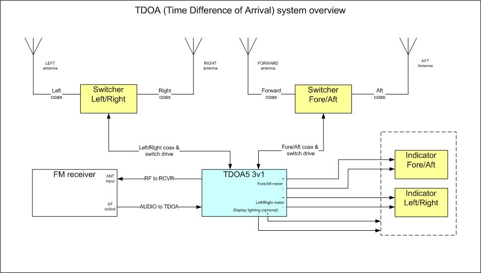
TIME DIFFERENCE of ARRIVAL (TDOA)
Schema's en technische beschrijvingen van ARDF apparatuur.
(voor sommige bestanden heeft u de SprintLayout viewer, sPlan viewer of Acrobat Reader nodig. Deze vindt u in de software sectie van deze website.)
TDOA 5 (Time Difference of Arrival) documentatie
Basic designs are from WB2HOL and VK3ZPF. Thanks to them I have been able to do al this.
The NEW 4v1 PCB layout has not been tested yet. Only in modified 3v1 setup. There may be small errors in the printlayout.
The 4v1 schematic is correct.
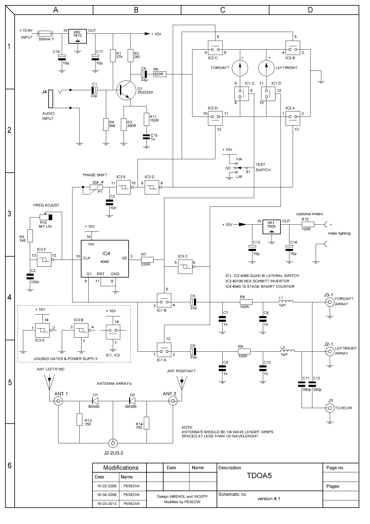
![]() TDOA5 4v1 schematics
and TDOA5
4v1 component layout & pdf
(prototype modifications to improve stability)
TDOA5 4v1 schematics
and TDOA5
4v1 component layout & pdf
(prototype modifications to improve stability)
![]() TDOA5 4v1 component
list (in RTF)
TDOA5 4v1 component
list (in RTF)
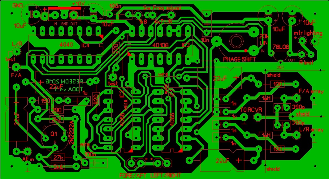
![]() TDOA5 4v1 printed circuit
board in PDF (Sprintlayout
file)
TDOA5 4v1 printed circuit
board in PDF (Sprintlayout
file)
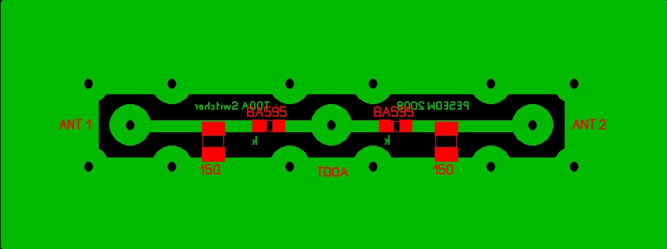
![]() TDOA5
antenna switcher printed circuit board (Sprintlayout
file)
TDOA5
antenna switcher printed circuit board (Sprintlayout
file)
![]() All files in one ZIP-file
(updated on 02-03-2016, but all is still in prototype phase and un-tested)
All files in one ZIP-file
(updated on 02-03-2016, but all is still in prototype phase and un-tested)
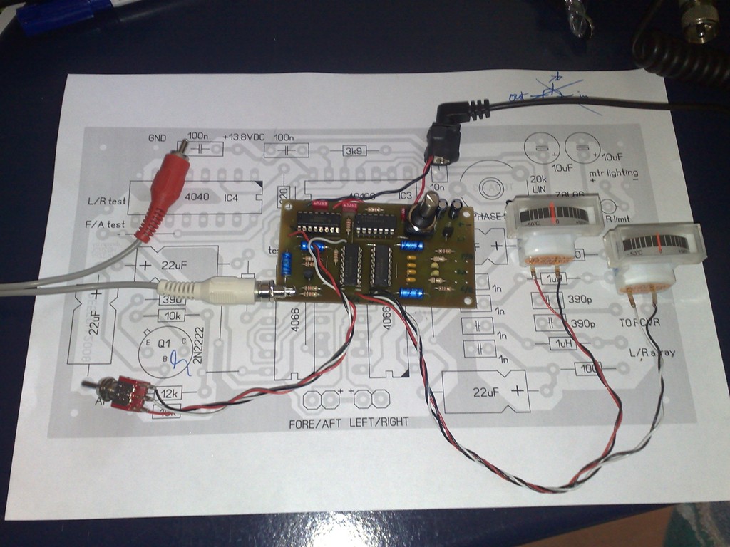
Here are some pictures that give an overview of the components used.
(click on the pictures to get a high resolution view)
|
v4.1 - Modifications to improve stability with adjustable antenna switch
frequency. |
v4.1 - Modifications to improve stability. (prototype) |
|
Antenne switcher
|
Test bench |
|
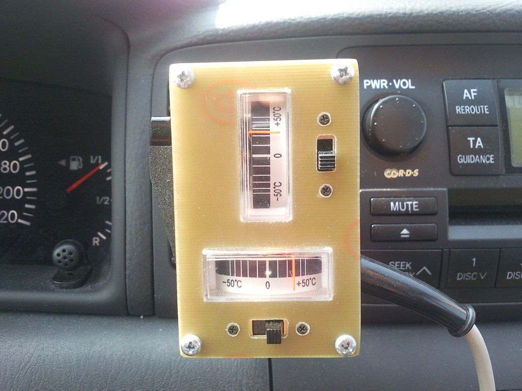
Display unit |
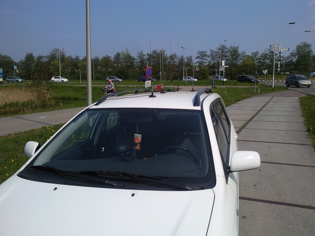
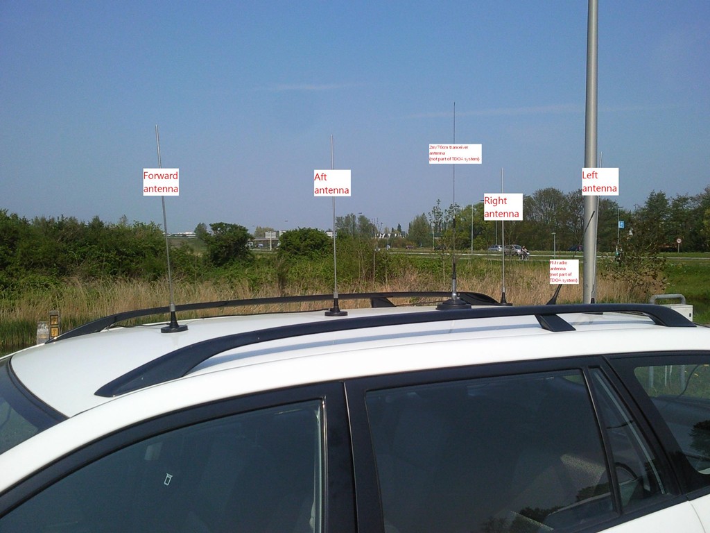
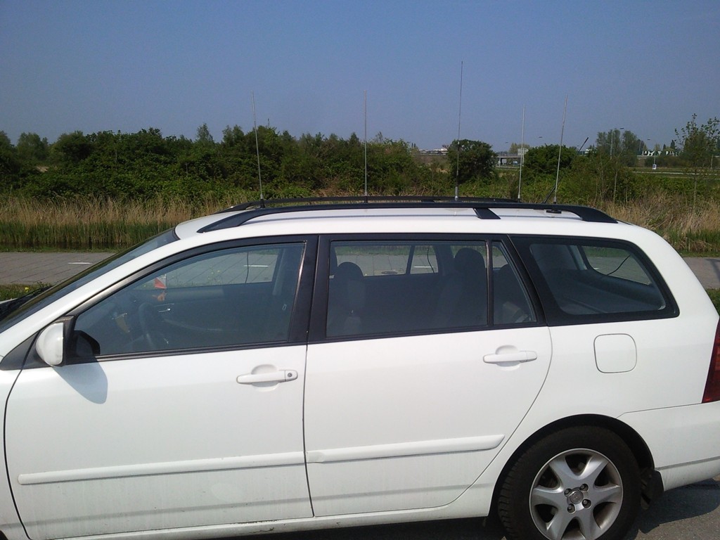
Antenna array mounting example |
|
Antenna array mounting example |
Antenna array mounting example |
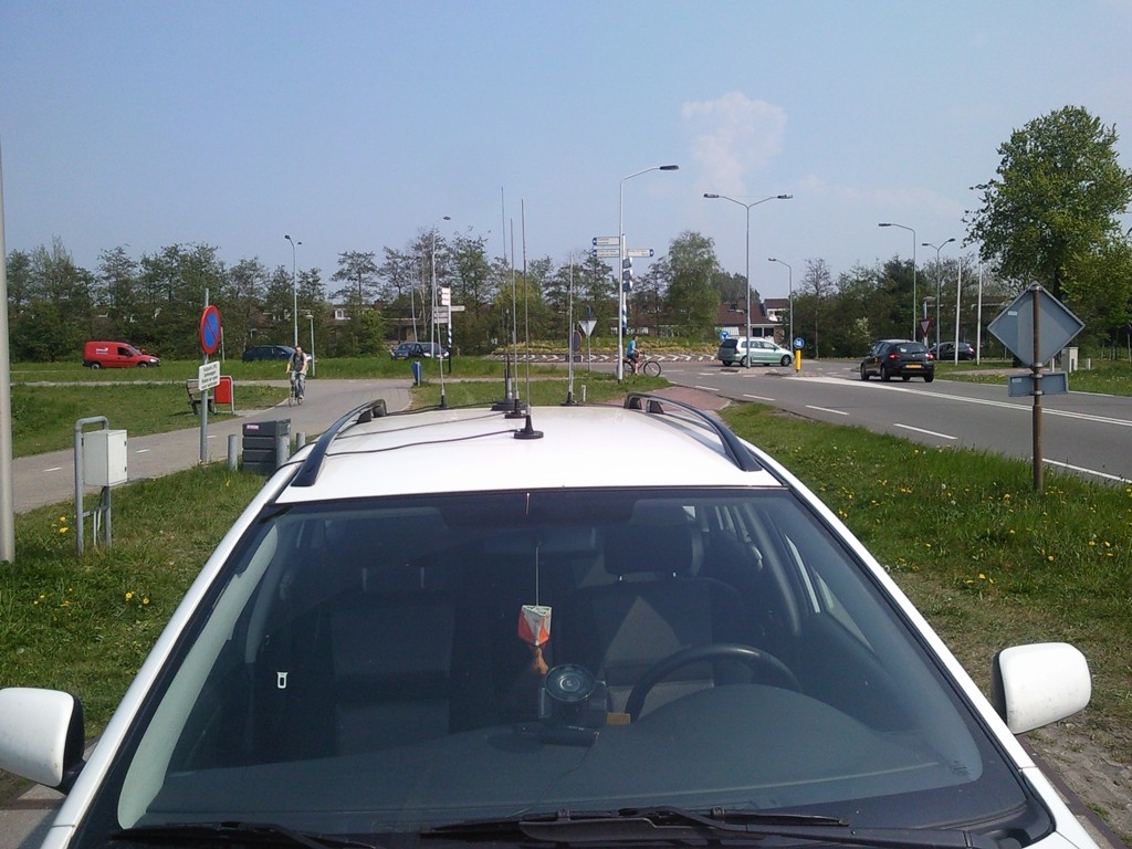
|
Antenna array mounting example |
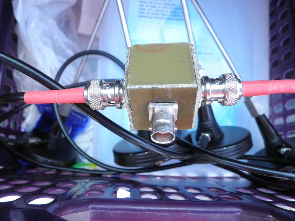
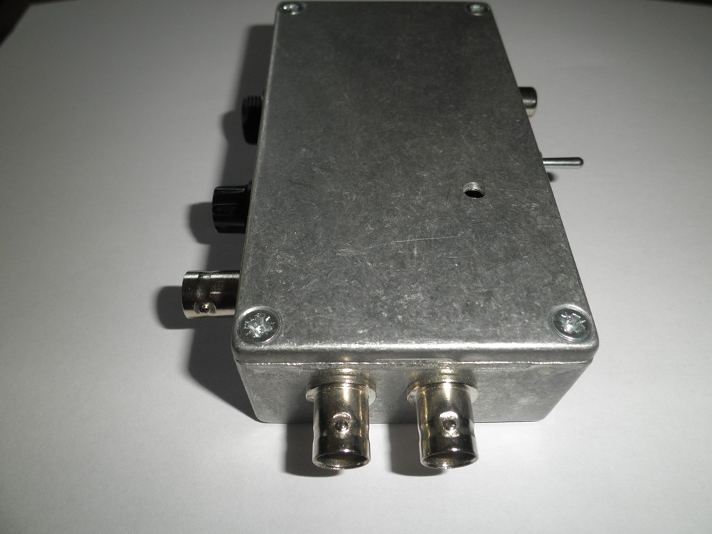
Antenna switcher with BNC connectors On the background some antennas |
|
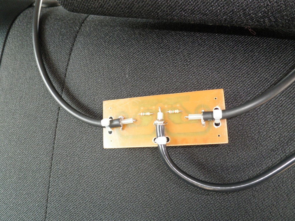
Antenna switcher |
Reverse side of the prototype switcher |
|
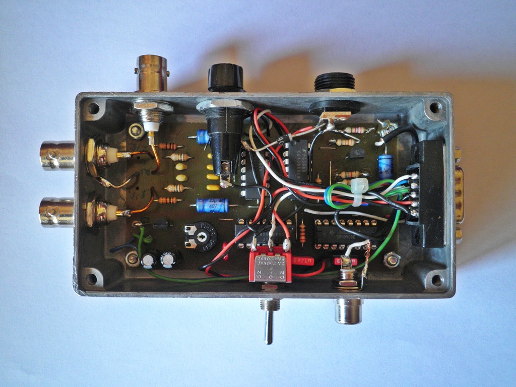
Top view of TDOA5 3v1 assembly |
Inside view |
|
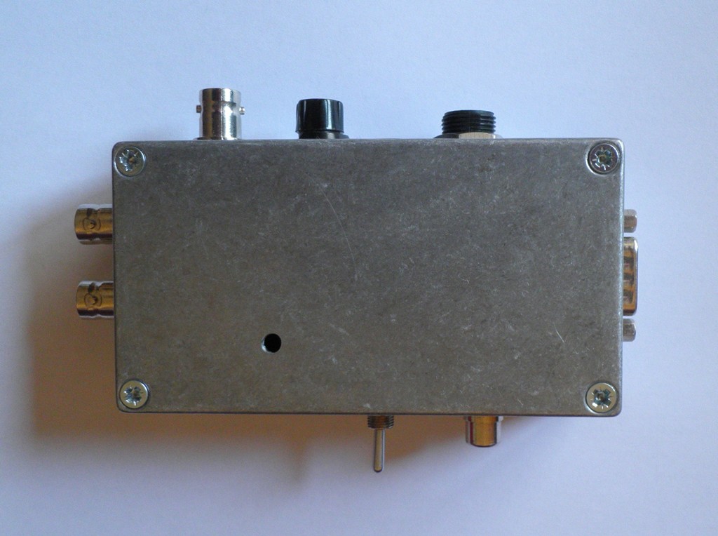
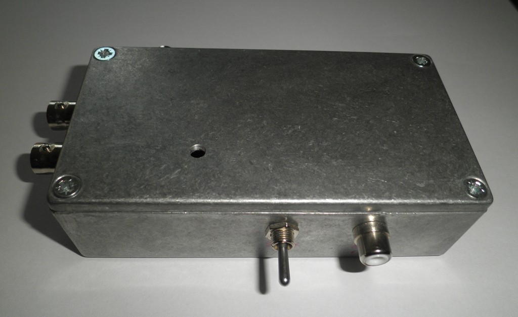
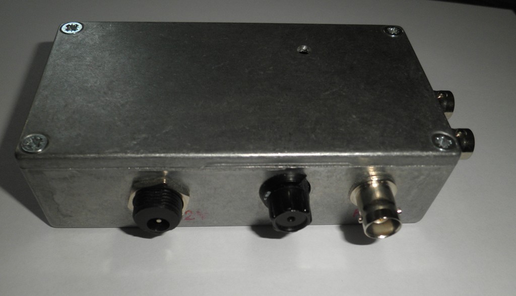
Test switch and audio input |
Power supply, fuse and RF output |
|
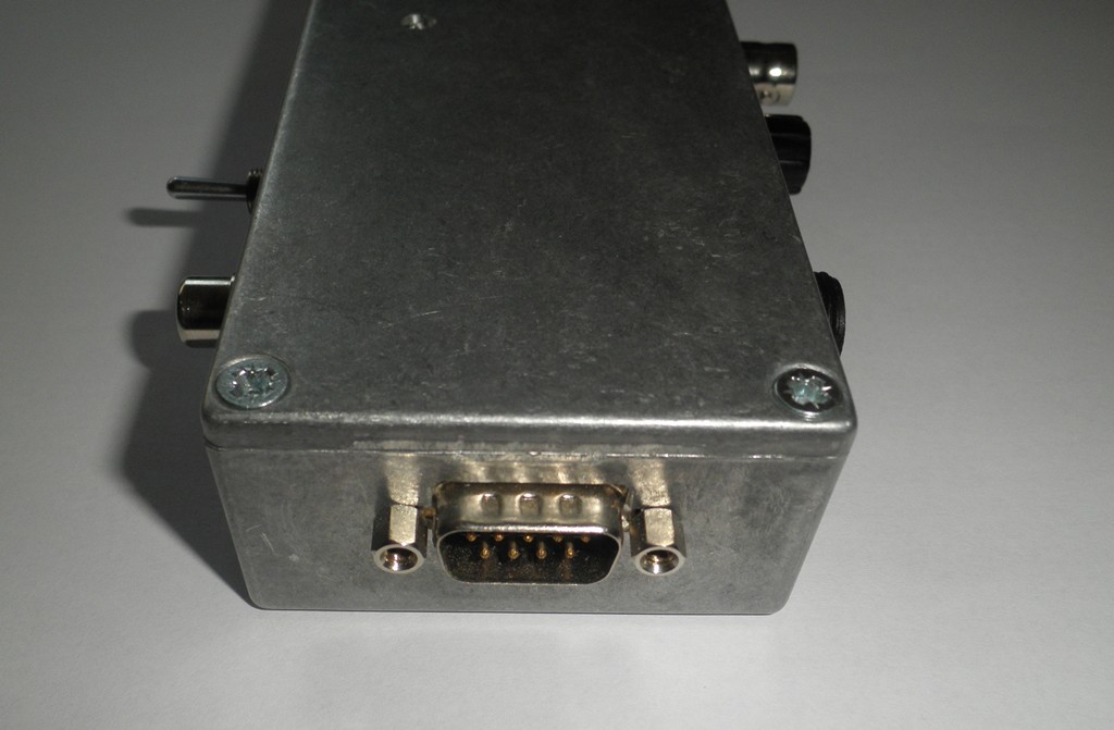
9-pins D-connector to the display unit |
Fore/Aft and Left/Right antenna connectors. |
<home or ARDF Techniek page >
Webmaster: Edwin (pe5edw@veron.nl) - Last update: 02-Mar-2016